MPG - LURGI MULTI PURPOSE GASIFCATION: APPLICATION IN "GAS-GASIFICATION"
2000 Gasification Technologies Conference San Francisco, California October 8-11, 2000
W. Liebner, Lurgi Oel·Gas·Chemie GmbH, Germany
D. Ulber, RWTH Aachen, Germany
INTRODUCTION
Multi Purpose Gasification "MPG" is a process for the partial oxidation of hydrocarbons delivering a synthesis gas composed mainly of carbon monoxide and hydrogen. Different -even unmixable- hydrocarbon-containing feeds can be gasified: ranging from natural gas, tars and other coal gasification residues, refinery residues, asphalts to slurries and chemical wastes.
With the versatility of MPG the feedstock flexibility has increased significantly: a refinery, for example, can now consider heavier crudes and deep deasphalting and MPG will convert all the concentrated "leftovers" into useful syngas. Additionally, wastes like tank sludges and contaminated (lube) oils can be disposed off in this unit, helping to create the truly clean refinery.
Similarly, chemical residues can be gasified, allowing the chemicals producer to re-utilise former waste streams and to comply with ever-raising environmental standards.
MPG is a modern development based on a technology acquired by Lurgi from SVZ (Sekundärrohstoff Verwertungs Zentrum Schwarze Pumpe) three years ago. For liquids gasification the burner -which is the core part of every gasification process- was re-engineered and newly patented by Lurgi. However, for gas-gasification the existing SVZ-burner was not considered suitable for large-scale applications. So, another burner from Lurgi's broad file of gas production processes was adopted and modified to become the MPG gas burner.
The paper discusses briefly the origin of the process and its
main features, concentrating on burner technology. It describes the adaptation
and development of the gas burner by computational fluid dynamics (CFD).
Finally, a survey is presented on the most promising applications of
gas-gasification.
MPG AT THE WASTE UTILIZATION CENTRE SVZ
MPG's origin and reference plant is SVZ where it has operated in liquids service for more than three decades and in "gas-gasification" mode for several years in between.
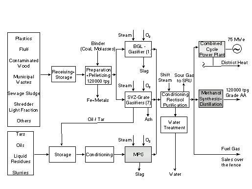
The origin of today's gasification installations at SVZ was a huge town gas production plant (Gas Works Schwarze Pumpe, GWSP). The plant supplied about 75 % of the total town gas demand of the former GDR, based on gasification of locally available lignite. As reported earlier (Ref. 1), the plant has been converted stepwise to treat an extremely wide variety of solid and liquid wastes and to produce methanol and electric power.
The block flow diagram in Fig.1 roughly summarises the plant configuration at SVZ. It is shown here to emphasise the gasification section with three processes (Fig. 2):
Figure 1: Waste Utilization Centre at SVZ
It is important to note the situation in pre-SVZ times: at GWSP only lignite was gasified and the only product was town gas. There were three oil gasifiers in operation (pre-MPG), one of which for several years was run on natural gas to boost the capacity of the complex. This is the reason why MPG existed at SVZ as fully functional oil and gas gasification process.
Figure 2: Gasifiers operated at SVZ
MPG: "GAS-GASIFICATION" RE-INVENTED
On the basis of the core elements of MPG technology and the long term experience gained in SVZ Lurgi has developed the process further to be able to adapt it to different feedstocks and gasification conditions (described in detail earlier, Ref. 2):
As described above, a gas burner was acquired as part of the technology. On closer scrutiny it was found that it was well suited to the special reactor configuration at SVZ but did not lend itself easily to scaling and rigorous CFD-modelling. This was required above all for the intended large-scale application but as well for standardisation.
The solution was found in-house: one of Lurgi's oldest and most successful gas production technologies is Autothermal Reforming (ATR) which in essence is a catalytic partial oxidation process. This mostly is oxygen-blown and is used either for methane (NG) reforming or for secondary reforming downstream a tubular reformer (SMR). These applications use large gas flows (in the order several 100,000 Nm3/h) routinely as well as hot (about 650°C) CO- and H2-rich feedgas, the latter in secondary and combined reforming. The experience with high feed temperatures at high CO partial pressures translates into a deep knowledge of metal dusting phenomena, a knowledge necessary to optimise heat recovery by highest feed temperatures and careful material selection. An important advantage of the ATR-burner is its "internal cooling", so it does not need a water cooling system. This design was kept for the Gas-MPG-burner as well.
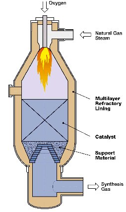
The burner being of prime importance for this process also, it was designed and modelled using the emerging CFD programs already a decade ago. This was an advantage for the transformation of the ATR-burner to a MPG-burner. Fig. 3 shows a Lurgi ATR with its characteristic feed/burner system. This had to be converted into the more compact shape of the MPG-burner. One important feature of the ATR-burner was maintained for the new application as well, the swirl flame which is induced by special vanes within the burner channels.
With that, the profound operating experience of both, the gas-gasification at SVZ and the Lurgi-ATR in its many installations are combined into the new Lurgi Gas-MPG.
Figure 3: Lurgi ATR
CFD MODELLING OF ATR AND GAS-MPG - INCLUDING VERIFICATION
By modelling of the Lurgi Autothermal Catalytic Reforming (ATR) process the correct position of the catalyst in a minimum-sized reactor is specified and the change in swirl number, angle and direction can be studied in order to achieve fast mixing. Choosing an inappropriate swirl may cause a circulating flame. Also the geometry of the reactor vessel can influence flame stability.
Moreover, for optimum operation, the velocity, concentration of species and temperature should be uniform at the inlet of the catalyst section.
The model developed in cooperation with Prof. May (University of Darmstadt) is based on the fluid transport equations for mass, three components of momentum, enthalpy, species concentration and turbulent quantities. In the turbulence model the formulation of mean Reynolds stresses is used to describe turbulent diffusion. The oxidation reactions of various hydrocarbons in the feed and oxygen are taken to occur instantaneously. The gas mixture in fuel rich regions is determined by the water-gas reaction
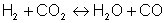
and by the methane reaction

where the equilibrium constants are strongly temperature dependent.
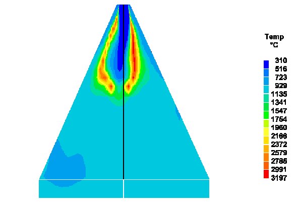
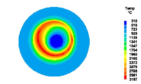
The model was verified by confirmation of the conditions during an accident in an operating reactor (Ref. 3): a material failure caused a channel blockage and led to a change in the burner outlet condition which was followed by an unstable flame (Fig. 4,5). The result was a burnout in the conical reactor section. Fortunately, there were no injuries and the material damage was limited. Although impressive, this type of model verification is not recommended.
Figure 4: Modelling of ATR - vertical cross-section of unstable flame
Figure 5: Modelling of ATR - horizontal cross-section of unstable flame
Modelling the new burner design for the non-catalytic partial oxidation of gaseous hydrocarbons (i.e. MPG) is necessary as the steam-to-fuel- and oxygen-to-fuel-ratios differ from those used in the catalytic partial oxidation process (Table 1).
|
ATR |
Gas-MPG | |
|
pressure [bar] |
35 |
70 |
|
temperature inlet [°C] |
750 |
500 |
|
temperature outlet [°C] |
950 |
1400 |
|
O2 / natural gas [mol/mol] |
0.4 |
0.7 |
|
steam / natural gas [mol/mol] |
1.5 … 1.7 |
0.05…0.2 |
Table 1: Comparison of Lurgi´s catalytic and non-catalytic partial oxidation processes
The model equations can be taken from the simulation of ATR, only the geometry and boundary conditions have to be adapted.
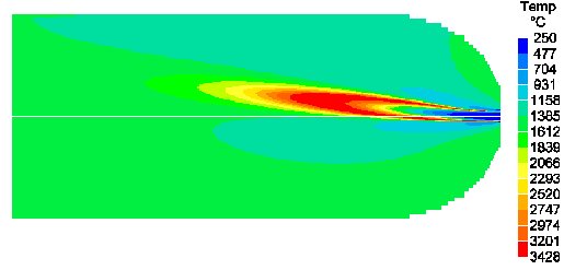
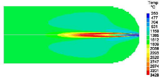
The calculations ensure that the temperatures in the recirculation zone do not exceed the limit of the reactor lining in a minimum-sized reactor by finding a stability region for the flame. Again different modes of operation can be evaluated (Fig. 6, 7).
Figure 6: Modelling of non-catalytic partial oxidation (MPG) - unstable flame caused by insufficient swirl
Figures 6 and 7 give an impression how the stability of the flame is influenced by its momentum (swirl) which again depends -among others- on shape, number and position of the vanes inside the gas channels. A design study has to consider all these parameters and their interactions thoroughly.
Figure 7: Modelling of non-catalytic partial oxidation (MPG) - stable
flame
GAS-MPG - THE PROCESS
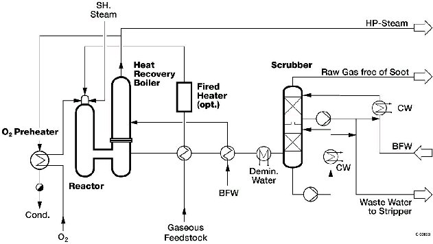
Following the theoretical considerations and CFD computations, the newly designed Gas-MPG burner and rector were integrated into a practical flow sheet. (Fig. 8) The main deviations to the original SVZ flow sheet are the omission of the burner cooling water system and the inclusion of a heat recovery boiler instead of a quench. While the water quench at SVZ was necessary because of the alternative high-slag liquid feedstock it would lead to a waste of energy in gas-only application. Thus, the "boiler-configuration" of MPG is applied here. This new flow sheet already is implemented with current projects.
Figure 8: Simplified flow sheet - MPG Gas-gasification
The simplified flow sheet (Fig.8) shows the main features of Lurgi Gas-MPG. A gaseous feedstock which may be natural gas or waste/recycle gases or any combination thereof is preheated by the hot raw gas and an optional fired preheater. Preheat level and use of the fired heater are determined by energy and cost optimisation. This considers the relative values of feed, fuel gas and oxygen. Oxygen also is preheated using a small amount of hp-steam from the heat recovery boiler. Feed gas and oxygen enter the reactor together with a minor amount of "shielding" steam via the new gas burner. Gasification occurs in the empty, refractory-lined reactor at temperatures between 1200°C and 1400°C. The high-level heat is recovered in a specially designed fire-tube boiler raising saturated high-pressure steam. The remaining heat is used for preheating feedstock, boiler feed water and demin water. Finally, a water-scrubbing tower removes traces of soot, HCN and NH3.
Soot formation in the process is extremely low, so that no special filtration is necessary with the wastewater passing to a sour-water stripper and final treatment.
A desulfurisation unit is not shown in this flow sheet. It may be located either upstream or downstream of the gasification, depending again on the heat utilisation as described above and on the material selection for the equipment in areas prone to metal dusting.
|
|
Feed |
Product | |
|
Composition, vol%: |
CO2 |
1.00 |
4.40 |
|
CO |
31.09 | ||
|
H2 |
60.16 | ||
|
N2 |
1.93 |
0.73 | |
|
CH4 |
88.01 |
0.38 | |
|
C2H6 |
6.85 |
||
|
C3+ |
2.21 |
||
|
S S max. |
5.2 |
ppmv | |
|
LHV, MJ/Nm3: |
38.37 |
10.55 | |
|
Temperature, °C: |
15 |
60 | |
|
Pressure, bar: |
30 |
68 |
Table 2: Gasification of European pipeline natural gas using 99.5% O2 and a trace amount of steam
As an example, table 2 shows the results of the gasification of natural gas using high purity oxygen and a small amount of shielding steam. The cold gas efficiency of the gasification unit itself is at 84.5%. In addition to that high-pressure steam is raised at a rate of 2.1 kg/Nm3 of feed gas. Together, these values prove the high energy efficiency of a well-designed process.
APPLICATION OF MPG GAS-GASIFICATION
Generally speaking, gas-gasification -a non-catalytic POX- competes in many applications with catalytic POX (ATR) and even catalytic steam methane reforming (SMR). The main distinguishing parameter among the three is the obtainable H2/CO ratio: 3 to 6 and higher for SMR, 1.8 to 3.7 for ATR and 1.6 to 1.9 for Gas-MPG. These values may vary with feedstock and possible recycle stream but they give a first indication which process may be favoured. This will mostly be the process which delivers a synthesis gas composition nearest to the one required.
This can be understood when considering the whole gas production process chain: in addition to the gasification or reforming unit this comprises gas cleaning like acid gas removal and gas composition adjustment like shift conversion, membranes or PSA. Any process which saves on these secondary units will have a cost advantage.
A simple example might illustrate the point: Oxoalcohol synthesis gas has a H2/CO ratio near unity, so, oil-gasification which delivers this directly, is favoured above all processes with higher H2/CO ratio as long as the additional hydrogen can not be utilised economically. From this reasoning two groups of prospective applications for gas-gasification emerge:
Real-world projects often will fall in both categories and see additional restrictions and boundary conditions. In any case it is important that the process selection is made with due consideration of all technical and economical characteristics. Under such conditions gas-gasification will see a fair share of the future syngas market.
References: